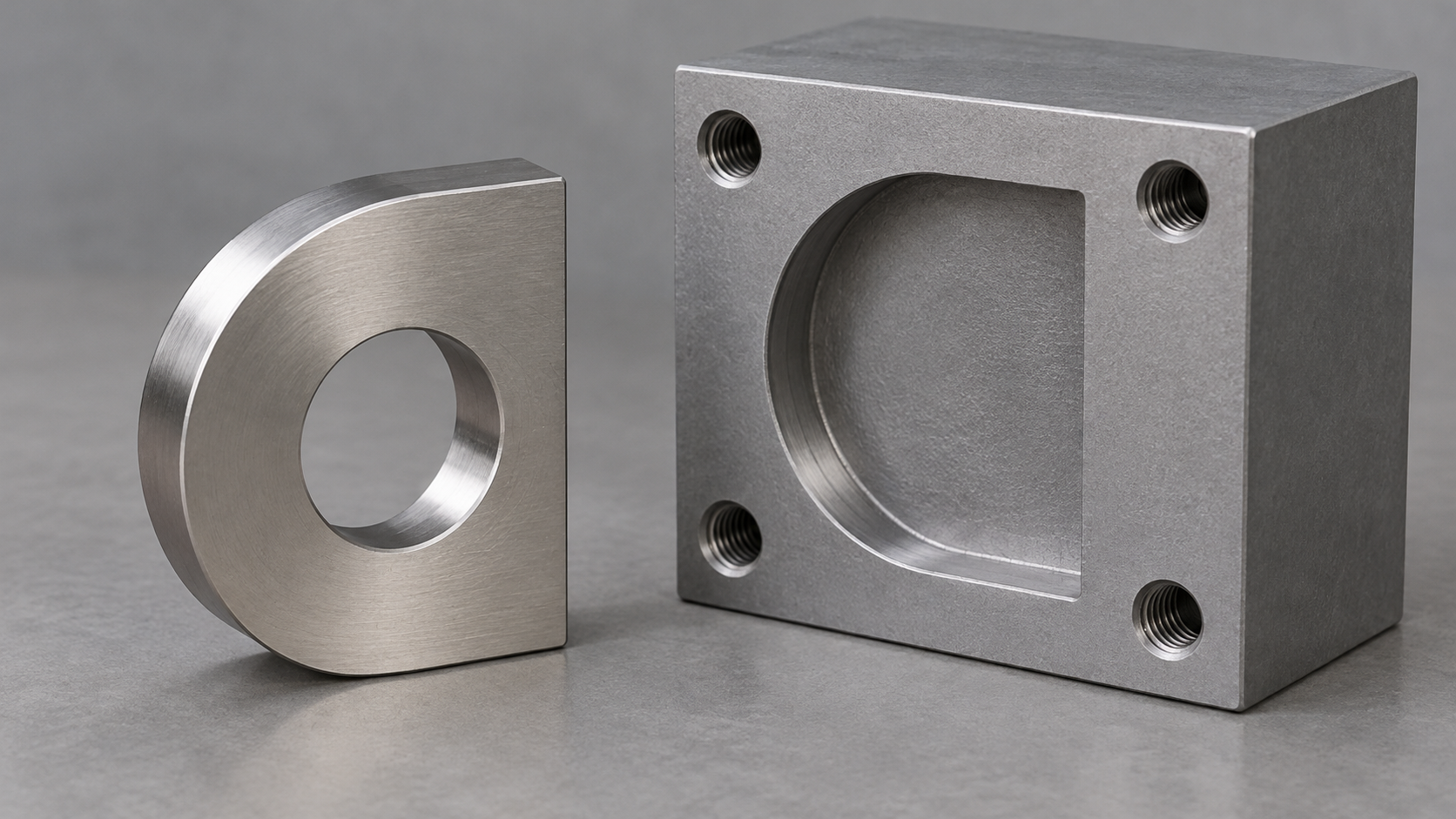
A component that fits in two directions but works correctly in only one can create avoidable assembly confusion. When reviewing a stainless replacement for brass, ask whether the shape can make the intended orientation easier to recognize or physically guide. Start with the mistake you want to prevent, then evaluate the proposed feature in the actual assembly.
A useful change might involve a distinct outline, a locating feature, or a clearer relationship to the mating part. It is not enough to add an arrow to a drawing and assume the problem has disappeared. The operator, tools, surrounding components, and work sequence all belong in the review.
Describe the actual confusion
Ask assembly colleagues to show the point where uncertainty occurs. Does the part look the same from both ends? Can it enter the opening backward? Is a left-hand version easily confused with a right-hand version? Record the observed problem without attributing it automatically to operator carelessness.
Use the current component and surrounding parts to explain the situation. Note the orientation in which the part arrives at the workstation and whether gloves, limited visibility, or a fixture obscure useful features. A clear description can reveal that the difficulty begins with presentation or picking rather than the component shape alone.
Our assembly-trial guide covers evaluation of the complete change. This article focuses on one question within that trial: can the design or presentation make a specific incorrect assembly less likely while preserving correct installation and servicing?
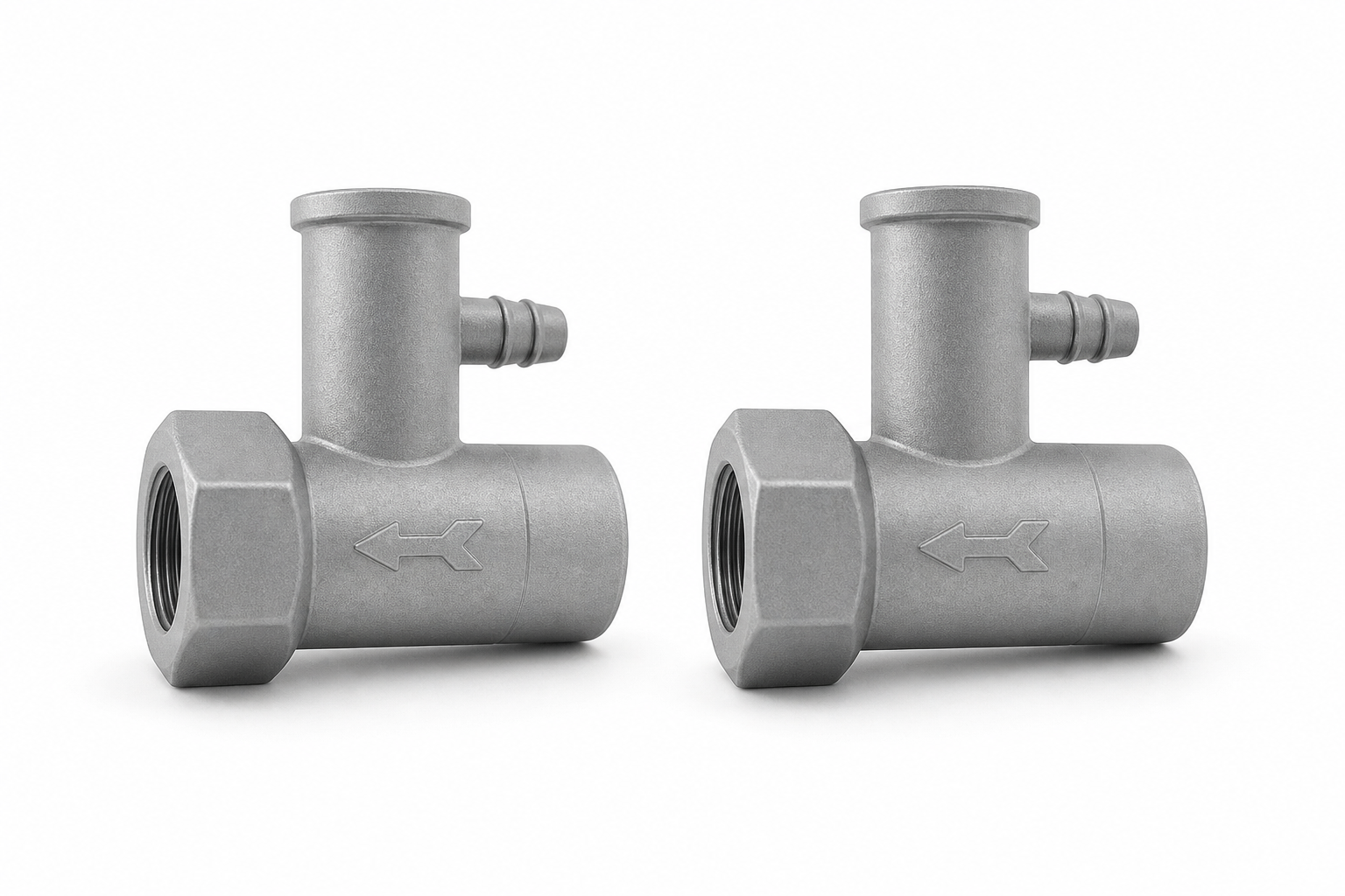
Conceptual illustration: two metal valve bodies with directional arrows on their sides.
Ask about useful shape differences
Metal Injection Molding (MIM) shapes metal powder mixed with a temporary binder in a mold, then removes the binder and heats the powder into a solid metal part. MIMA introduces the process. For a small complex component, the supplier can assess whether an orientation feature could be included in the proposed shape.
CMG's design guidance describes complex geometries and formed markings. These possibilities support a discussion, not a guarantee that every locating feature is practical. Ask for a marked proposal showing the feature and explaining the specific assembly problem it is intended to address.
Compare options before selecting one. An asymmetric outline may help recognition; a feature engaging with the mating component may guide positioning. A packaging change could also be relevant. Have the product team evaluate the alternatives rather than treating an extra feature as automatically superior.
Distinguish a cue from a physical restriction
A visual cue helps someone recognize the intended direction. A physical restriction may prevent a particular incorrect position. Keep those functions separate in the review. An arrow hidden after the part is picked up cannot be assumed to prevent reversal, and an apparent key may still allow an unintended partial insertion.
Ask what happens if the part is presented incorrectly. Can the operator tell before applying force or installing the next item? Could an attempt damage either component? Have the responsible team assess those questions using a safe trial method appropriate to the product; do not improvise a destructive check on production equipment.
Our component-marking guide explains identification. A mark can support orientation, but the current question is whether the complete assembly interaction works as intended. Record what the mark or feature actually does and what the operator must still check.
Preserve correct assembly and service access
Review the proposed shape with the normal tools, fasteners, and surrounding parts. Check that a new projection does not block tool access or make the component awkward to hold. A feature that prevents one mistake can introduce another problem if it changes the work sequence without being noticed.
Include disassembly where the product is intended to be serviced. Confirm that the orientation feature remains understandable after the product has been used and that the approved replacement can still be installed. Do not assume a feature hidden during production assembly will be obvious to a service technician later.
For a hypothetical small mounting lug, an off-centre locating detail could help distinguish the front face. The team should still check its clearance, handling, and relationship to the mating part. The example illustrates a review question; it does not establish an approved design for another product.
Run a focused comparison
Compare the current and proposed arrangements using a clearly described task. Ask assembly colleagues to demonstrate picking, orienting, placing, fastening, and checking the component. Observe where they hesitate or seek confirmation. Record the findings with the sample revision and the conditions of the trial.
Avoid claiming an error reduction percentage without a suitable measurement basis. A small demonstration can reveal an obvious difficulty, but it does not establish performance across all operators, shifts, or product variants. State the questions answered and the work still needed before production approval.
Include the supplier in the explanation of any requested revision. A photograph of the installed part with the problem marked can be more useful than a request to make assembly easier. Keep the revised feature connected to the quotation and approval package so the reviewed shape is the one ordered.
Decide whether the feature earns its place
Accept the change only when the responsible team is satisfied that it addresses the intended problem without creating unacceptable effects elsewhere. Consider component cost, any additional tooling work, operator instructions, and the effort needed to qualify the new arrangement. A simpler presentation change may sometimes be sufficient.
To explore the options, send LP MIM the current part and a description of the orientation problem. Include the mating components and normal installation sequence. The most useful proposal makes the intended action clearer and gives your team a practical way to verify the improvement.
Comments
Loading comments...