Metal injection moulding From part design to production
Complex geometry. Considered material choices. A clear route to production.
We help engineering teams develop and manufacture complex metal components. LPMIM is the international brand of Lingpeng New Materials Limited, based in China.
What is metal injection moulding?
MIM shapes fine metal powder mixed with a binder, removes the binder and sinters the component.
It offers a manufacturing route for complex metal geometry when design, material and repeat demand justify tooling and qualification.
Read the process and selection guideFrom fine powder to a dense metal component.
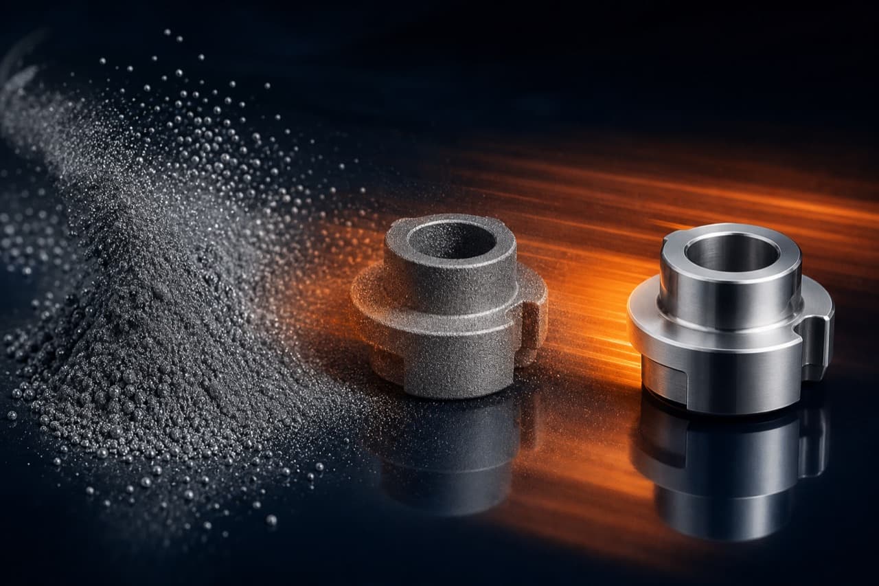
Powder and binder become MIM feedstock. Injection moulding creates a grey-black moulded part; debinding and sintering then remove the binder and densify the metal with controlled shrinkage.
- 01
Metal powder
Fine metal particles are the starting material.
- 02
MIM feedstock
Powder is mixed with binder and made into pellets.
- 03
Injection moulding
Heated feedstock is injected into the mould.
- 04
Moulded part
A grey-black, binder-containing “green part” is ejected.
- 05
Debinding
Binder is removed, leaving a fragile porous part.
- 06
Sintering
Controlled heating bonds the particles and densifies the part.
- 07
Sintered MIM part
The same geometry is smaller after controlled shrinkage.
Is your component a candidate?
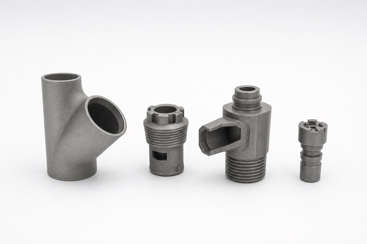
Small components with multiple features, recurring machining operations or opportunities to combine parts are worth reviewing. Very low volumes, changing designs and large simple shapes can favour another route.
Explore custom MIM partsFunction first.
Then the material.
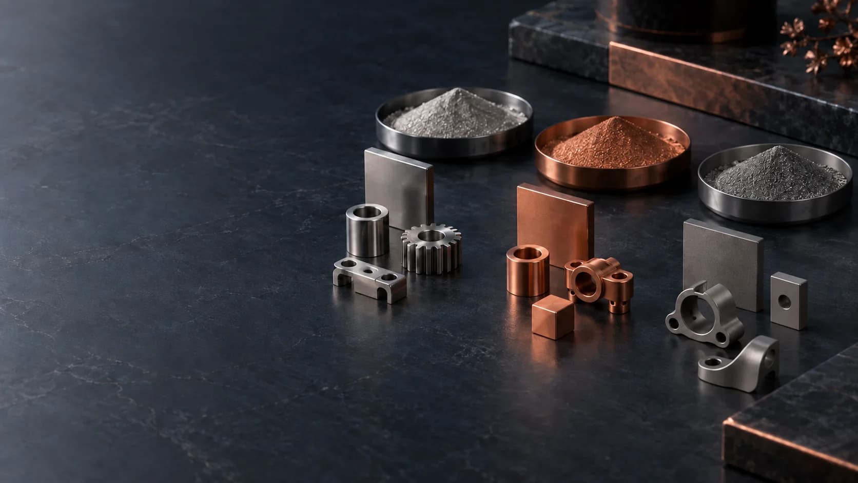
Compare corrosion, strength, conductivity and processing requirements. Confirm the exact grade and manufacturing route for your project.
Open the materials guideStainless steel
Corrosion exposure, strength and surface condition.
Copper MIM
Conductivity, density and residual contamination.
Titanium MIM
Material condition and a qualified sintering route.
Material family illustrations. Availability and finished-part properties require project-specific confirmation.
Define the project before committing to tooling.
- 01
Requirements
Share the application, material goals, critical features and anticipated demand. A discussion can start without a drawing.
- 02
DFM and production route
Review mouldability, sintering support, secondary operations and material selection.
- 03
Tooling and samples
Agree scope, responsibilities and a first-article inspection plan.
- 04
Production readiness
Confirm acceptance criteria, traceability, delivery requirements and change control.
Better information.
Better manufacturing decisions.
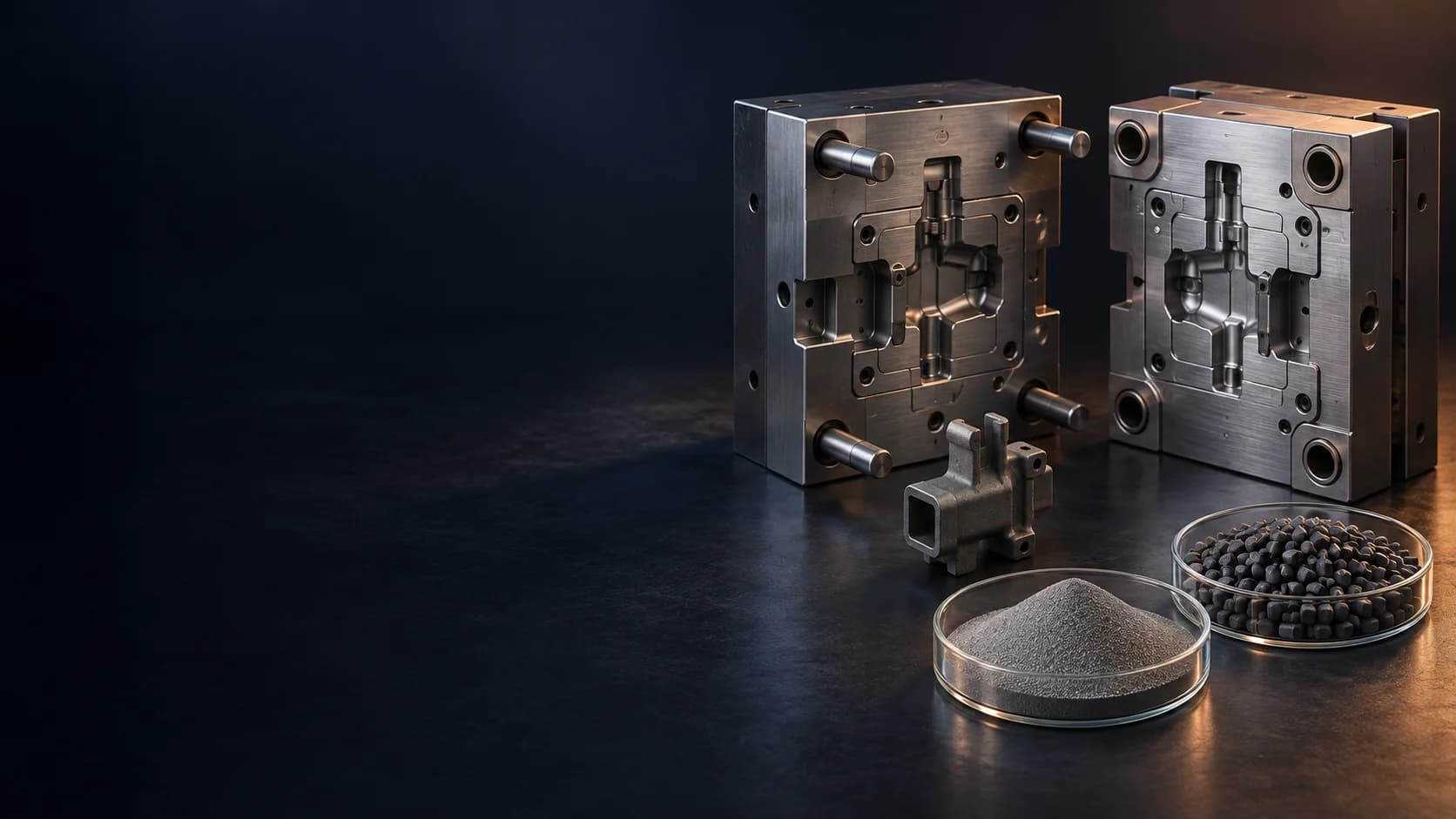
Metal injection moulding
The process, its strengths and its limits.
MIM Materials
Match material properties to the function of your component.
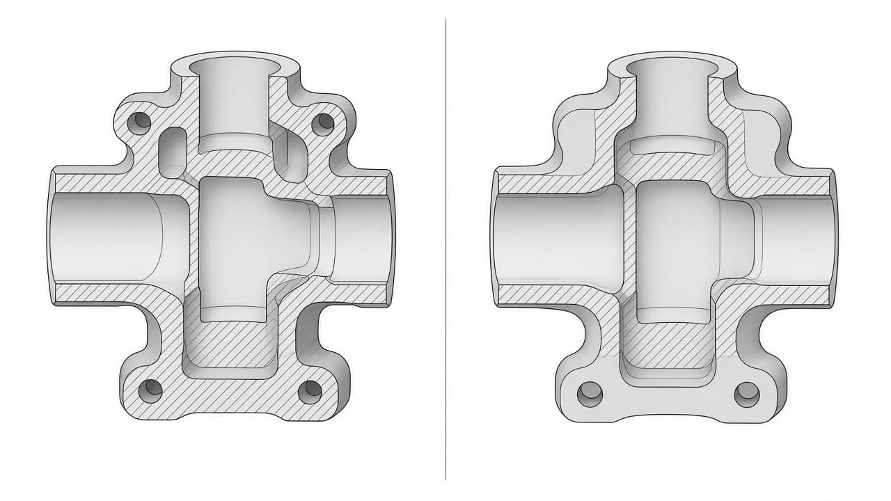
Design for MIM
Walls, features, sintering support and critical interfaces.
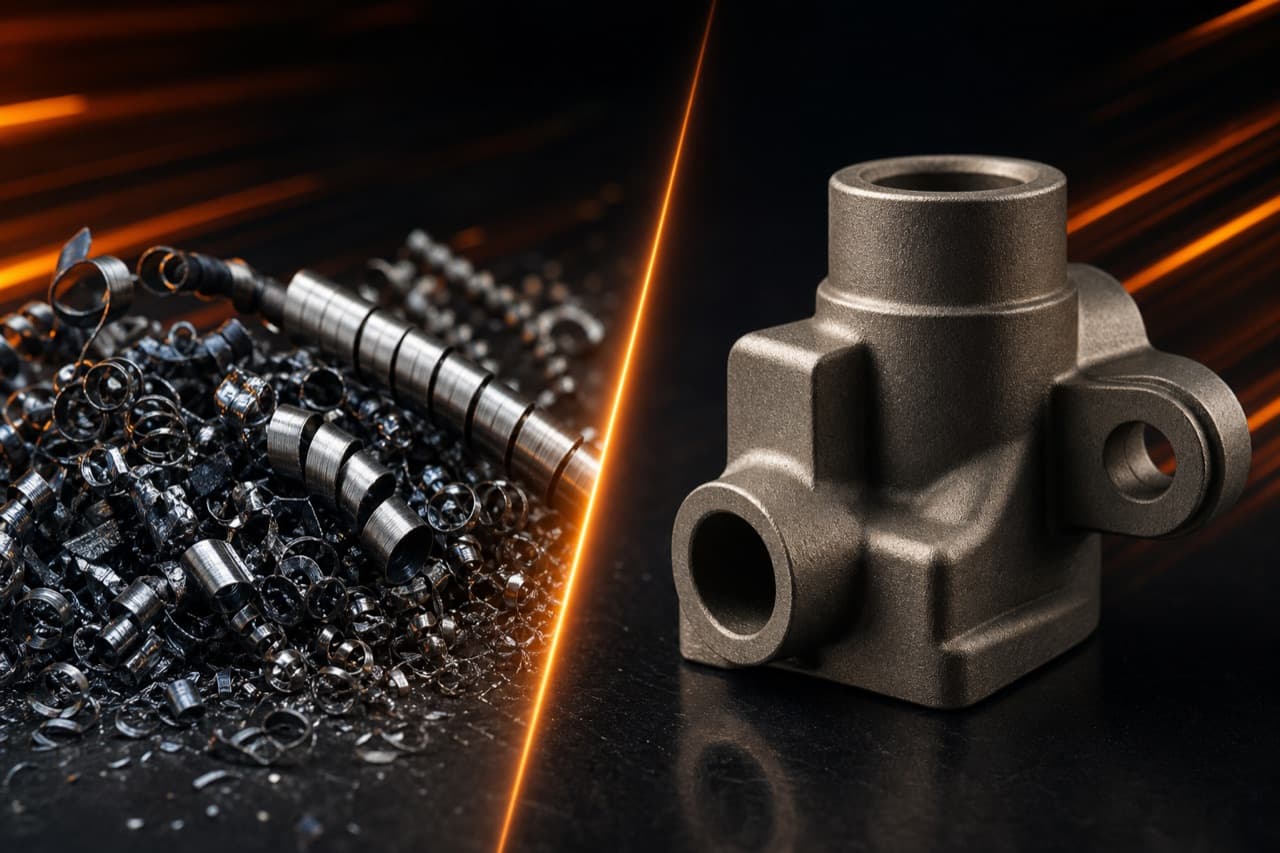
MIM vs CNC
Tooling, recurring cost and secondary operations.
Start with the environment
your component works in.
Qualify the specific component using agreed drawings, material records and inspection requirements.