CNC machining stays the right answer for prototypes and many low-volume metal parts. It becomes expensive when small complex components need many operations, long cycle times and high chip waste — year after year. Metal Injection Molding enters the conversation when tooling payback can beat that recurring CNC cost on a frozen design.
This article is a decision framework. It is not a price list. For the commercial comparison landing page, see MIM vs CNC machining.
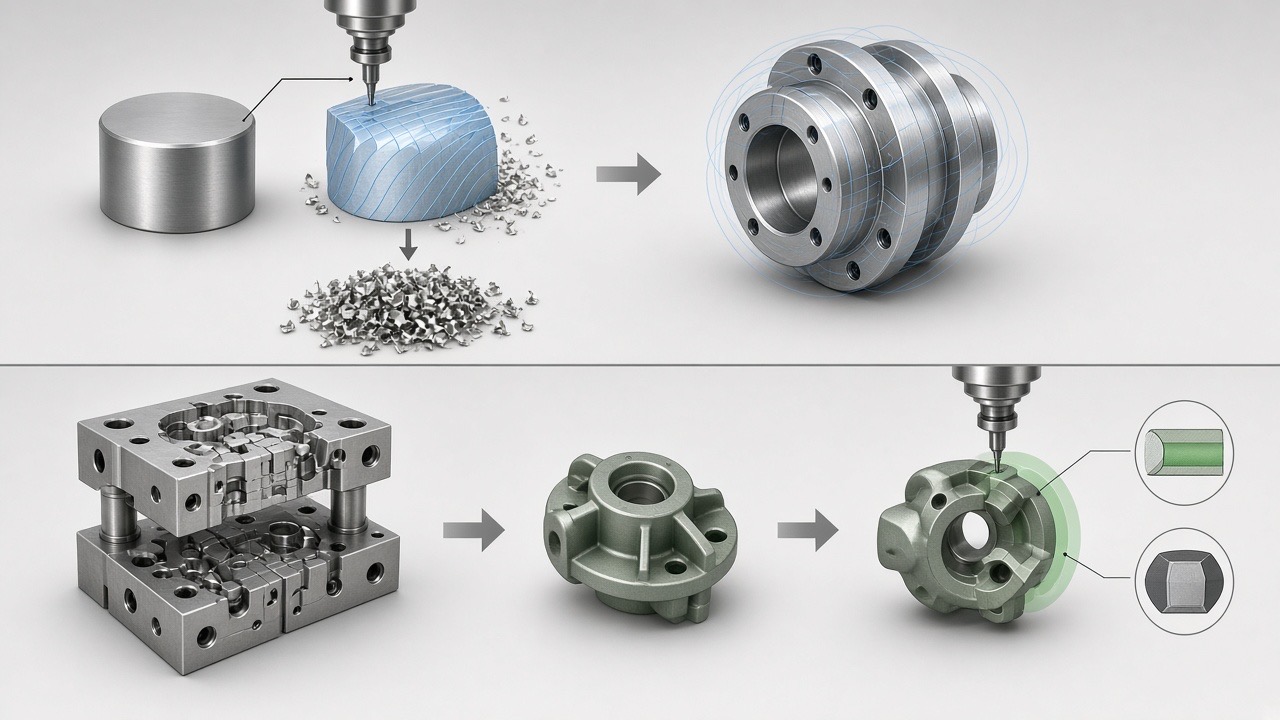 Conceptual process comparison: subtractive CNC path versus MIM tooling and near-net production.
The manufacturing problem
A typical CNC cost stack for a small complex part includes:
- Bar or billet material
- Chip scrap (especially brass and stainless)
- Multiple setups and fixtures
- Tool changes and cycle time
- Inspection after each critical feature
- Scrap and rework
MIM replaces much of that with feedstock, molding, debinding, sintering and targeted secondary machining. You pay for tooling up front. The economics only close if the design is stable enough to amortize that tooling.
When CNC becomes expensive
Review MIM when several of these are true:
- Annual demand is repeatable, not a one-off project
- Geometry is small and complex (pockets, ribs, internal features)
- Chip waste or expensive alloys inflate material cost
- Multiple CNC operations dominate manufacturing minutes
- Fixtures and changeovers create capacity bottlenecks
- Design freeze is realistic within the tooling lead time
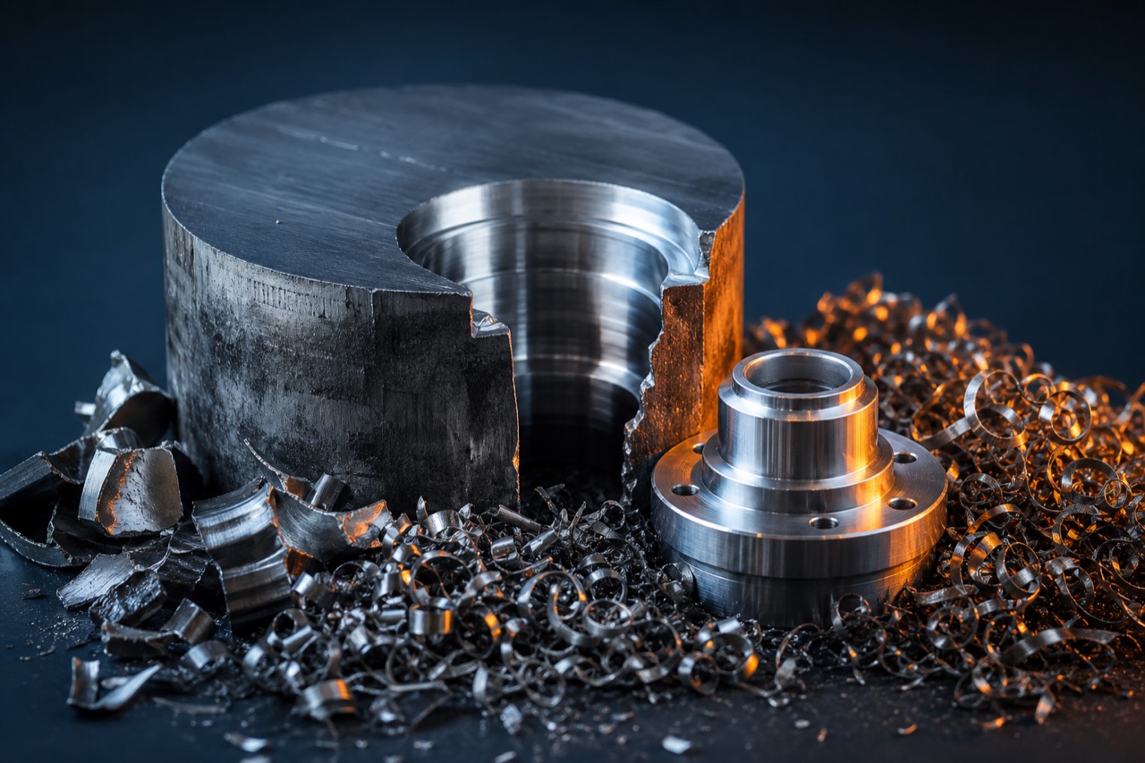 High chip waste is a common reason OEMs compare MIM to CNC on brass and stainless parts.
Which components are suitable for a payback review
| Annual volume stability | Geometry complexity | Tooling economics | Typical recommendation |
|---|---|---|---|
| Low / uncertain | Any | Weak | Stay CNC or soft tooling |
| Medium, growing | Simple | Weak–mixed | CNC until design freezes |
| Medium–high, stable | Complex | Stronger | Model MIM vs CNC carefully |
| High, multi-year | Complex, consolidatable | Strongest | Strong MIM candidate |
| High | Simple turned shapes | Often weak | Screw machine / forge may win |
| Any | All-over tight tolerances | Weak if heavy secondary | Hybrid or stay CNC |
“High” and “medium” are relative to your tooling quote and CNC cycle time — not a published universal piece count.
What your product team should check that change the math
1. Secondary machining
If threads, sealing faces, press fits or precision bores still need CNC after sintering, include those minutes in the MIM route. A fair comparison is often MIM + targeted machining versus full CNC, not “as-sintered versus as-machined.”
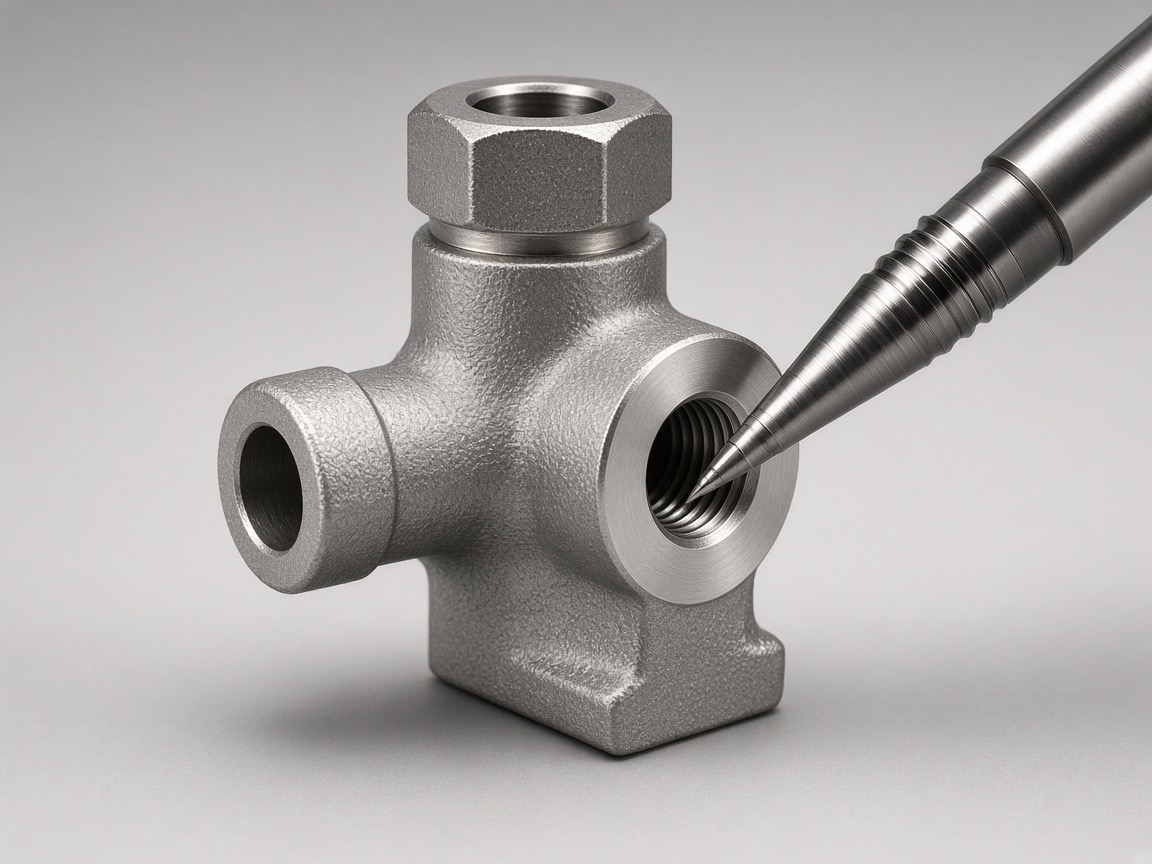 Conceptual: near-net MIM body with machining limited to sealing or thread interfaces.
2. Design freeze
Hard tooling punishes late changes. If the product team still iterates weekly, CNC protects schedule. MIM belongs after envelope, ports and sealing strategy stabilize — see design for MIM.
3. Shrinkage and dimensional planning
MIM parts shrink substantially from green to sintered size. Cavities are oversized to compensate. Exact shrinkage depends on feedstock, solids loading, geometry and sintering profile and must be validated in tooling trials. Do not treat post-compensation dimensional capability as the same number as total sintering shrinkage.
4. Material and brass programs
Many payback studies start from expensive brass CNC parts. Material index risk and scrap amplify CNC cost. See replace brass with MIM and MIM cost reduction.
Cost considerations — the payback model
Build a side-by-side model with your data:
| Cost element | CNC route | MIM route | Notes |
|---|---|---|---|
| Tooling / fixtures | Soft fixtures, maybe hard fixtures | Injection mold + possible sinter fixtures | Amortize over program life |
| Material | Bar/billet + scrap | Feedstock utilization | Alloy and scrap differ |
| Primary process | Cycle time × rate | Molding + debinding + sintering | Include yield assumptions |
| Secondary ops | Full machining stack | Targeted features only | Critical for fairness |
| Inspection / scrap | Per feature / lot | FAI then process control | Include qualification cost |
| Design change risk | Low for CNC | High if retooling | Soften with phased tooling |
Payback framing (qualitative): MIM tooling is justified when the present value of avoided CNC minutes, scrap and assembly steps exceeds tooling and qualification cost over the expected production life — at a design freeze you trust.
Calculate the expected payback using those inputs before relying on a single breakeven quantity.
Example decision framework
- Capture current CNC routing: operations, cycle times, scrap %, annual quantity, alloy.
- Mark features that must remain machined after any MIM conversion.
- Estimate MIM primary process + secondary machining (engineering judgment, then supplier quote).
- Add tooling and FAI cost; divide across program life (not only year one).
- Stress-test: −30% volume, +1 design change, heavier secondary machining.
- Decide: CNC, hybrid, or MIM.
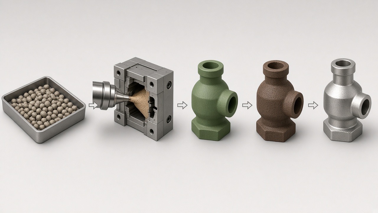 Conceptual MIM process chain used when modeling primary process cost.
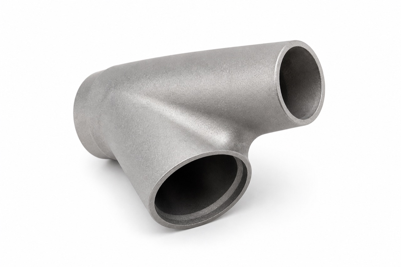 LPMIM product photography: complex connector geometry that is often expensive to machine from solid.
When to keep the current process
- Prototype and pilot builds where geometry still moves
- Very large or simple parts better served by casting, forging or machining
- Programs that cannot absorb tooling lead time
- Parts where secondary machining would approach a full CNC finish
- Uncertain demand that makes amortization speculative
What information LPMIM needs
For a MIM vs CNC route review, send via Upload Your Part:
- 3D model and 2D tolerance drawing
- Current CNC process notes (operations if available)
- Material
- Annual quantity and expected program life
- Which features are critical
- Current cost problem (cycle time, scrap, capacity, material)
We will indicate whether MIM looks suitable, suitable after redesign, or whether CNC / forging / casting remains the better path.
Start with your component
If your team is stuck arguing about a single “magic volume,” replace that argument with a cost-stack model. Upload a CNC-machined part for an engineering comparison, or start from the overview at MIM vs CNC machining.
Sources and scope
Prepared by LPMIM. This is a process-selection discussion, not a published customer test report or a performance guarantee. Validate material, dimensional and assembly requirements for the specific project.
Comments
Loading comments...