Teams sometimes ask for a “stainless version” of a brass valve body as if the only change were the alloy callout on the drawing. That approach fails in tooling trials. Brass-to-stainless Metal Injection Molding changes how the part is formed, how it shrinks, which features can be net-shape, and how the OEM qualifies the product.
This article explains the redesign work. For commercial replacement intake, use replace brass with MIM. For DFM intake, use design for MIM.
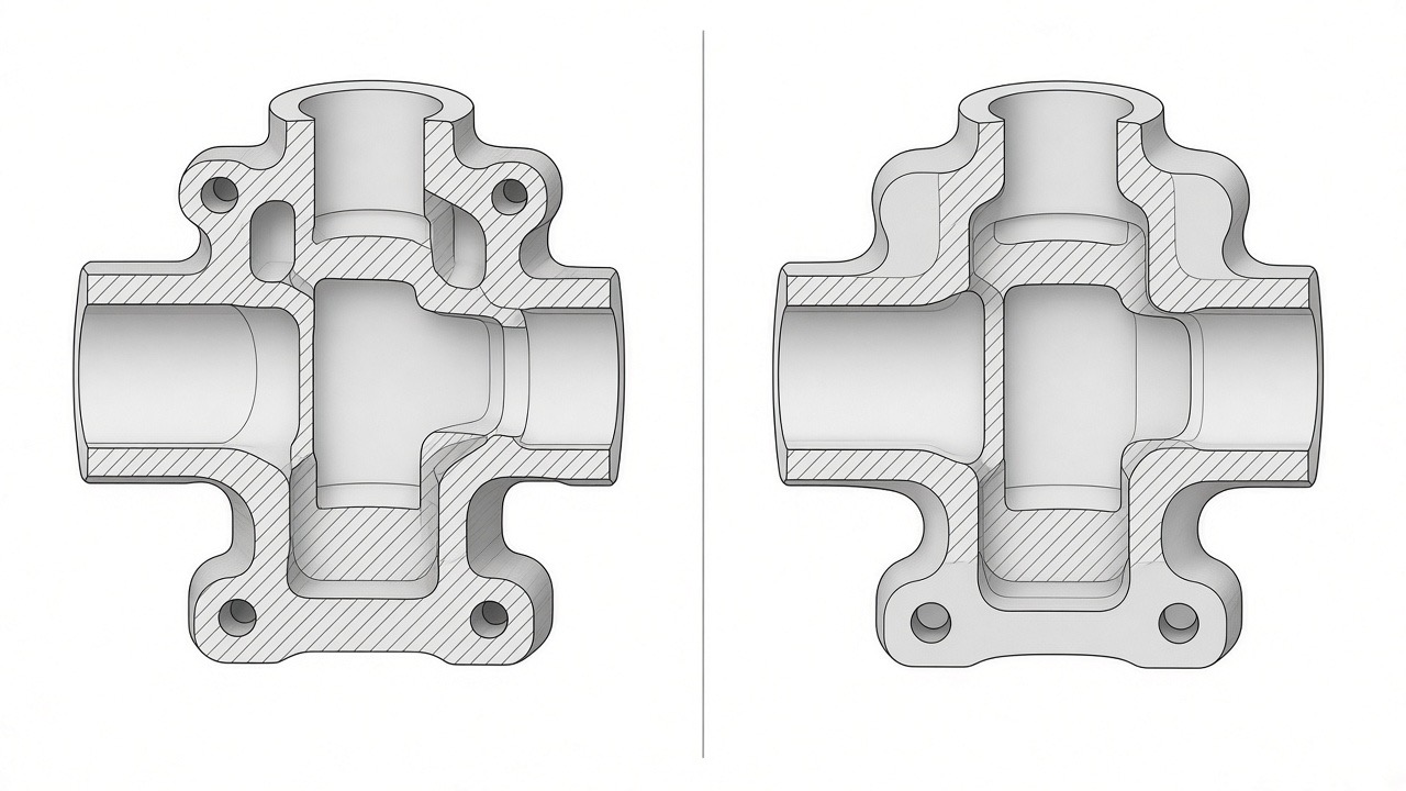 Conceptual cutaway: uneven brass-style sections versus more uniform MIM-oriented walls. Illustrative engineering schematic.
The manufacturing problem
Brass designs often assume:
- Excellent machinability
- Local thick sections that CNC can clear later
- Threads cut from solid
- Sealing faces finished as part of the machining route
- Familiar dezincification / plating behaviors
MIM stainless assumes:
- Moldable feedstock and ejection
- Substantial green-to-sintered shrinkage (cavity oversized to compensate; exact rate feedstock- and geometry-dependent; validate in trials)
- Preference for uniform walls and supported sections during sintering
- Near-net shape with planned secondary machining
- Passivation and stainless corrosion mechanisms instead of brass metallurgy
Copying the brass solid model into a MIM quote without redesign is how programs lose months.
When a “material swap” mindset becomes expensive
| Assumption | What actually happens | Cost / risk |
|---|---|---|
| Same walls as machined brass | Warp, sink, density variation | Scrap, retooling |
| As-sintered threads seal | Thread class / seal fail | Extra machining or redesign |
| Same envelope, ignore shrinkage | Dimensional miss after sinter | Cavity respins |
| “Stainless is always better in water” | Wrong grade or finish for chemistry | Field corrosion risk |
| Supplier “has NSF / UL” | Listing is usually assembly-level | Audit failure, launch delay |
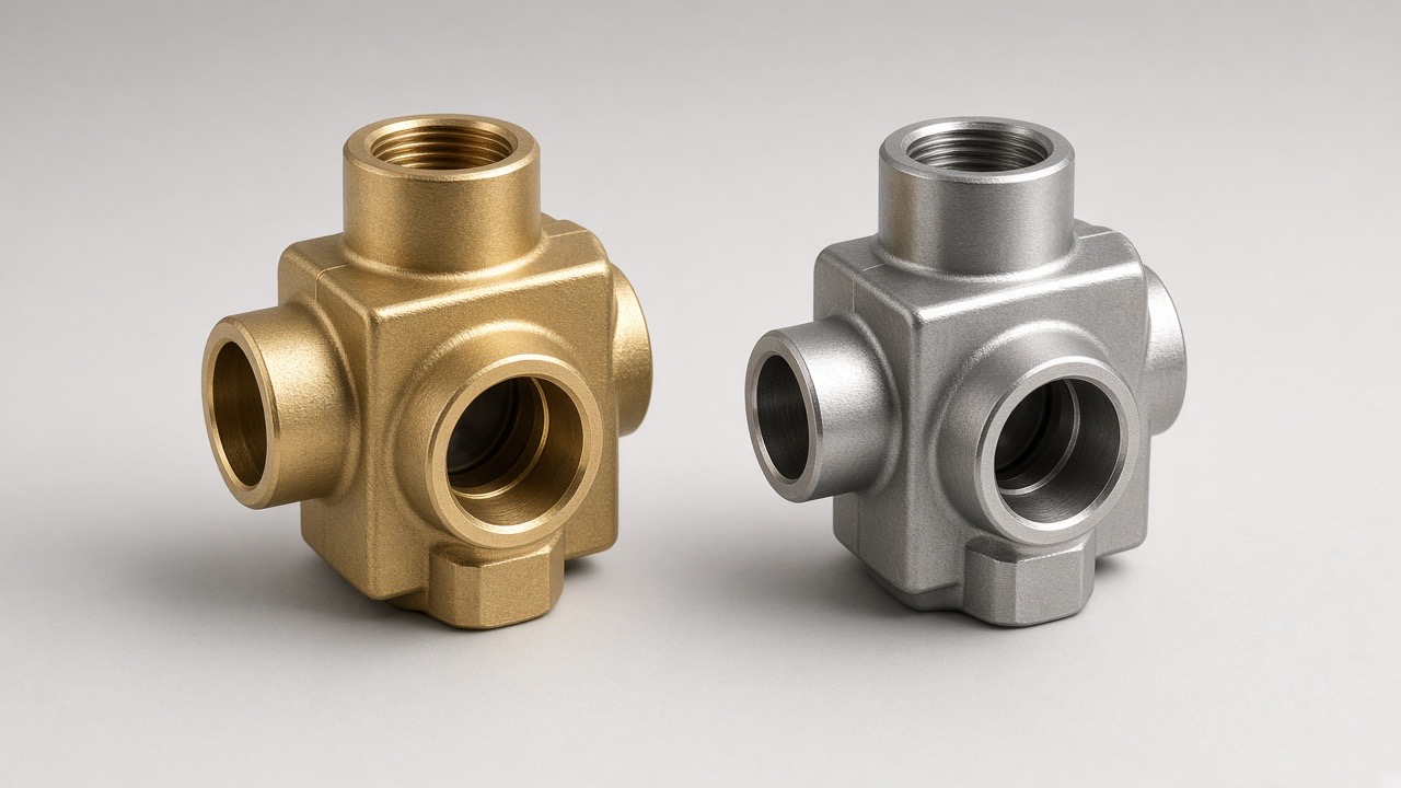 *Conceptual brass versus stainless component appearance. *
Which components can be redesigned successfully
Conversion programs work best when engineering can change:
- Wall thickness distribution and radii
- Internal cores and draft
- Gate and knit-line placement away from pressure faces
- Which faces are net-shape vs machined
- How assemblies consolidate (remove braze joints)
Typical candidates: valve internals, plumbing connectors, bathroom waterway bodies, manifold blocks — see fire protection valve components, plumbing components, bathroom hardware components.
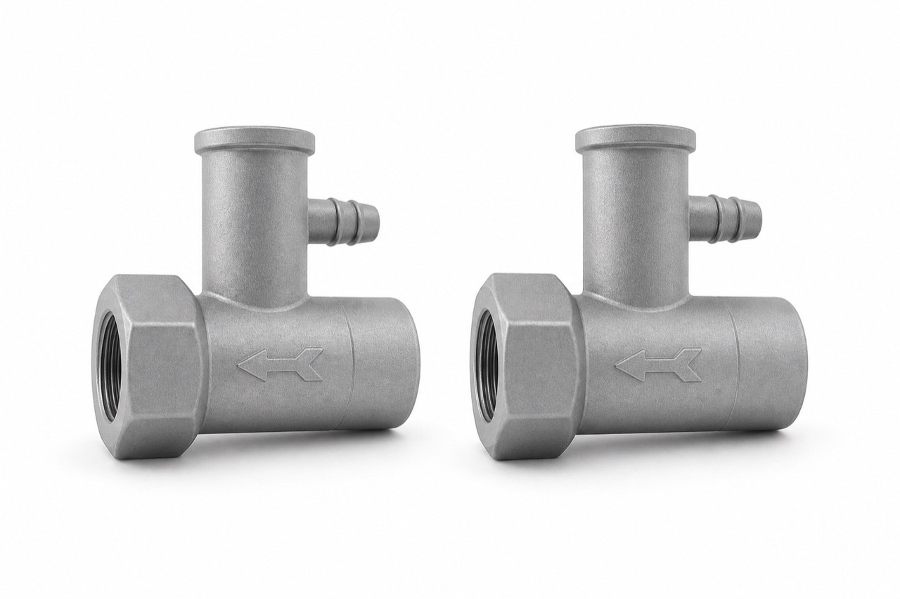 LPMIM product photography: manifold-style geometry where redesign can eliminate joints.
What your product team should check
Walls, draft and sintering support
Aim for more uniform sections; isolate unavoidable heavy masses; add draft on cores; plan sintering supports. Exact preferred thickness ranges depend on feedstock and geometry and should be confirmed in DFM — not treated as universal law.
Shrinkage — keep the concepts separate
- Total sintering shrinkage — molded size to sintered size; substantial; depends on feedstock, solids loading, geometry and furnace profile.
- Cavity compensation — mold oversized using expected shrinkage; refined after first articles.
- Post-compensation dimensional capability — residual variation around the compensated nominal; not the same number as total shrinkage.
Confusing these three is a common source of bad drawings and bad expectations.
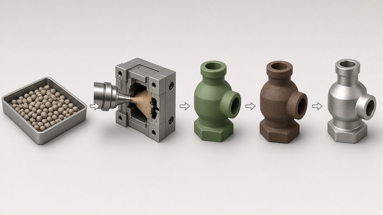 Conceptual process: molding, debinding and sintering drive both shrinkage and density outcomes.
Threads and sealing faces
Plan early:
- As-sintered thread form vs cut/rolled after sinter
- Seat and O-ring faces that need machining
- Press-fit diameters and concentricity callouts
- Surface finish requirements for seals
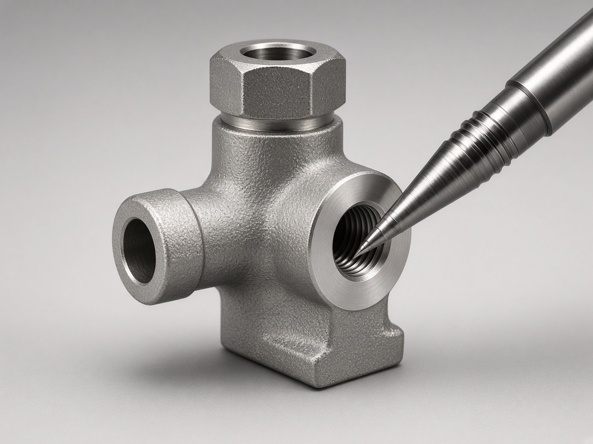 Conceptual: secondary machining limited to functional interfaces on a near-net MIM body.
Corrosion and alloy selection
- 304 is commonly reviewed for many water and fire-service environments when properly processed and passivated.
- 316L is often preferred where chloride exposure is more aggressive — application testing decides.
- 17-4PH may be considered when strength or wear dominates over maximum corrosion resistance.
See stainless steel MIM and MIM materials. Always validate against OEM water chemistry and standards; do not assume wrought-stainless handbook values transfer without process qualification.
Potable water and listing requirements
Confirm responsibilities before changing the production design:
- Request material identification, process controls and first-article data. Confirm current supplier certification, scope and validity separately.
- NSF / WRAS / regional potable requirements are typically owned by the OEM product or assembly program.
- UL / FM for fire products are typically assembly or listed-product pathways.
Engage compliance early so drawing callouts and test plans match the conversion.
Cost considerations
Redesign cost is real: engineering hours, soft iterations, pilot tooling, FAI, and possibly secondary fixture design. It is still often cheaper than discovering warp or seal failures after hard tooling. Compare:
- One-time redesign + tooling + qualification
- Versus ongoing brass material volatility + CNC + braze/plate + leak scrap
Estimate savings from the proposed design, quoted production route, and expected purchasing quantities.
Example redesign checklist
- Freeze functional requirements: pressure, media, temperature, seals, threads, mating parts.
- Audit walls and mass concentrations for sintering risk.
- Decide alloy (304 / 316L / other) from environment and spec.
- Mark net-shape vs machined features on a process drawing.
- Define FAI: density method, dimensions, passivation, pressure or leak tests as required by the OEM.
- Confirm certification owner and timeline.
- Only then release hard tooling.
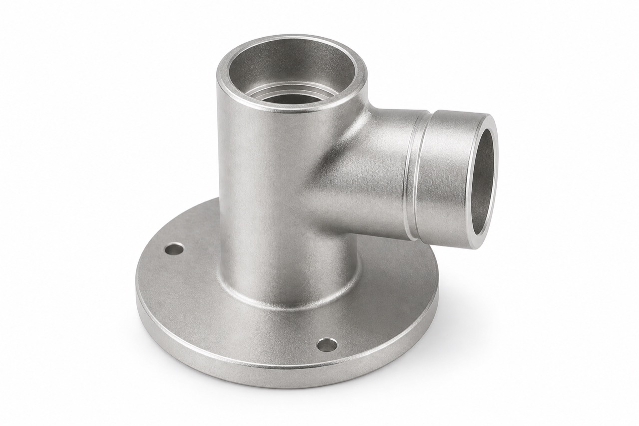 LPMIM product photography: fitting geometry where sealing and mating faces need an explicit machining plan.
When conversion should stop
Do not force MIM redesign when:
- Conductivity requires copper or brass performance
- The part is outside practical MIM size windows
- Volume cannot support tooling and qualification
- The organization cannot change the envelope or walls
- Listing timelines forbid a redesign cycle
Keeping brass (or CNC stainless) can be the correct engineering answer.
What information LPMIM needs
Upload via Upload Your Part:
- STEP / STP / IGES / 2D drawing
- Current brass alloy and process
- Annual quantity
- Pressure / media / temperature if known
- Tolerance and sealing requirements
- Certification targets (if any)
- What must not change in the envelope
We will classify the part as suitable for MIM, suitable after redesign, or better left as CNC / forging / casting.
Start with your component
If your drawing still says “same as brass, change to SS304,” pause. Upload the part for a redesign-oriented feasibility review, or start with the DFM overview at design for MIM.
Sources and scope
Prepared by LPMIM. This is a process-selection discussion, not a published customer test report or a performance guarantee. Validate material, dimensional and assembly requirements for the specific project.
Comments
Loading comments...