Start with function, not a manufacturing tolerance
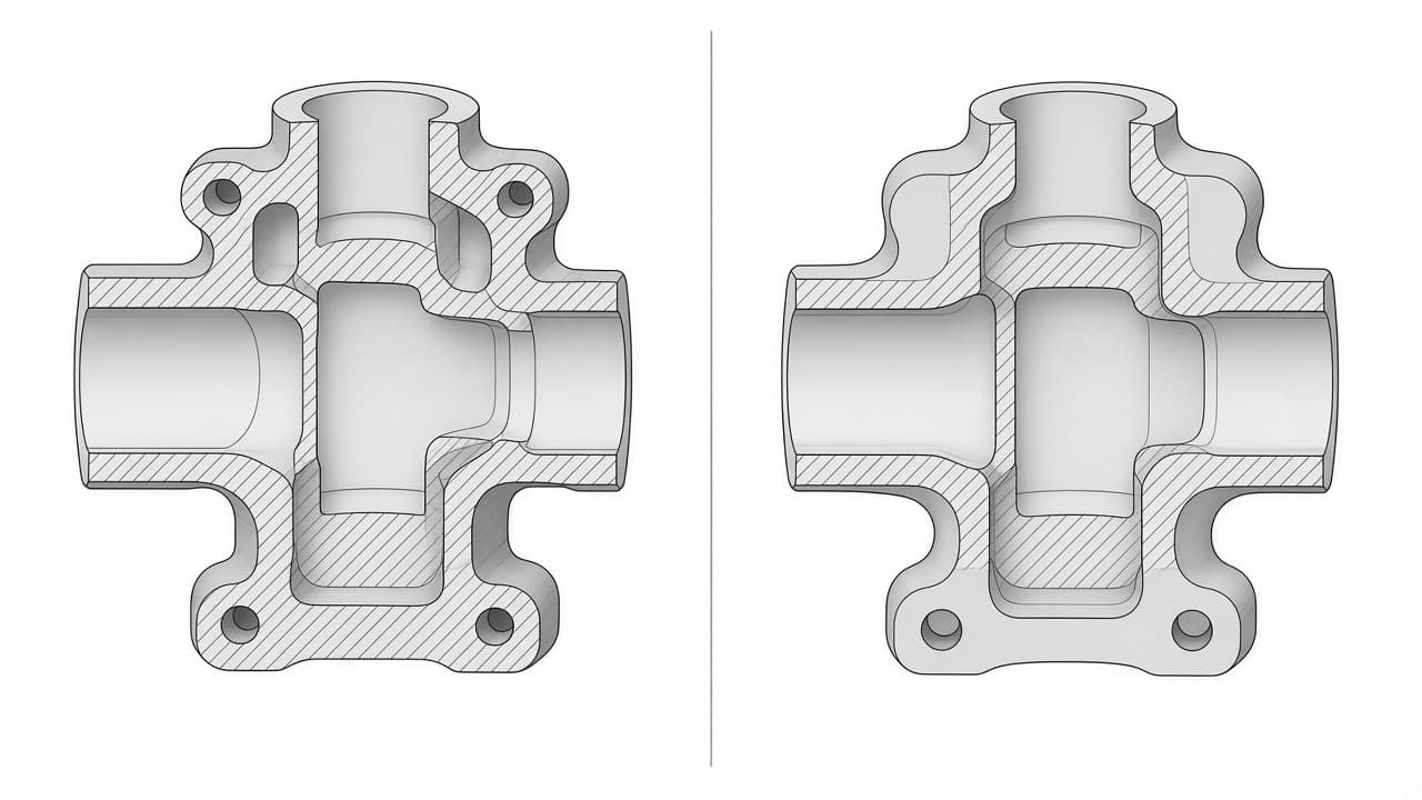
A MIM drawing should identify what each critical feature does: locate a mating part, carry load, seal a fluid path or provide a cosmetic surface. Separate these requirements from dimensions that can follow the molded geometry. Do not copy a machined design into hard tooling without reviewing how it fills, ejects and sinters.
Feature-by-feature design checklist
| Feature | Design approach | What to confirm |
|---|---|---|
| Walls and mass transitions | Favor uniform sections; core out isolated heavy masses where possible. | Fill path, debinding route, support and distortion risk; no universal wall thickness is promised. |
| Radii and ribs | Use gradual transitions and avoid unnecessary sharp corners. | Stress concentrations, powder/binder flow and ejection loads. |
| Holes and slots | Plan the core direction and access before fixing internal geometry. | Core stiffness, unsupported length and whether drilling is more reliable. |
| Draft and undercuts | Provide release surfaces; review slides or secondary operations for undercuts. | Tool complexity, ejection and the functional faces that must remain unchanged. |
| Gate and parting line | Locate away from important sealing or cosmetic surfaces where feasible. | Gate vestige, joining flow fronts and the proposed inspection plan. |
| Sintering supports | Provide a stable support strategy for the part during shrinkage. | Contact marks, orientation, unsupported spans and removal of supports. |
| Threads and sealing faces | Distinguish formed geometry from interfaces needing machining. | Thread class, sealing method, roughness, flatness and leakage requirements. |
Separate sintering shrinkage from dimensional capability
Green-to-sintered shrinkage is the change between the molded and final part. Tool cavities compensate for the expected change and are refined using trials. Residual variation around the compensated nominal dimension is a different quantity. Neither value should be copied from an unrelated feedstock or part.
The manufacturing review should identify the measurement datum, material state and any secondary machining before accepting a tolerance. A percentage alone does not define achievable GD&T on every feature.
Plan secondary operations before comparing cost
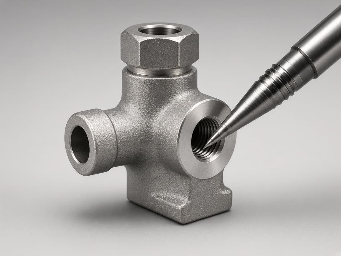
A useful route may combine near-net MIM geometry with machining of critical bores, threads or sealing faces. Include heat treatment, deburring, polishing, passivation or coating only where the drawing and application require them. Secondary operations add setup, inspection and handling costs.
What to send for a DFM review
- A 3D model and 2D drawing if available; an early concept can start the discussion.
- Material grade or required properties, operating environment and mating materials.
- Critical dimensions, datums, sealing surfaces and acceptable finish.
- Expected annual demand, batch size, design maturity and target schedule.
- A list of features that cannot change, plus inspection and qualification requirements.
Technical references
- European Powder Metallurgy Association — MIM process fundamentals
- European Powder Metallurgy Association — Introduction to MIM: materials, design and properties
Published by LPMIM. External references explain general MIM principles; they do not certify a supplier or a specific component. Material properties, tolerances and acceptance criteria must be agreed for each project.